The engineering problem
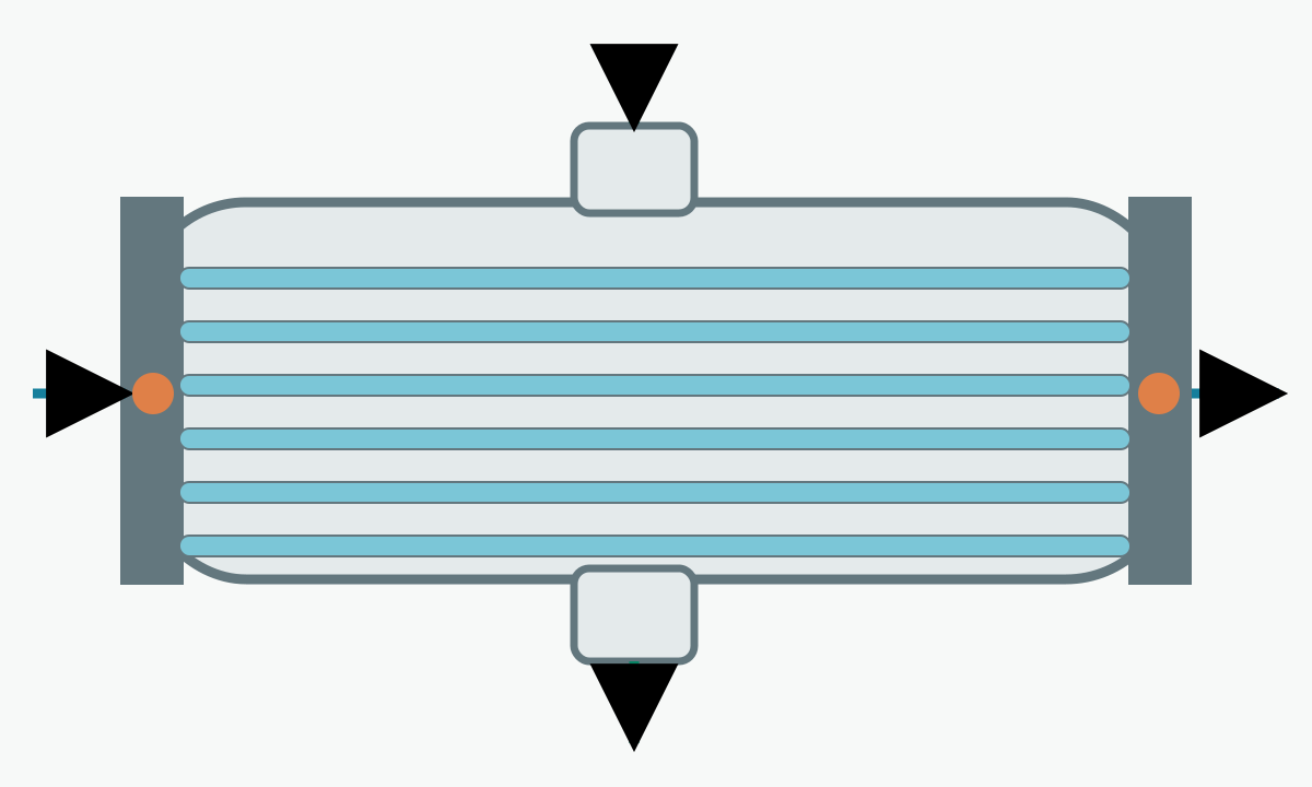
In a shell-and-tube heat exchanger, the tube bundle and tube sheets form the boundary between the tube-side and shell-side spaces. Depending on the design, tubes may be joined to a tube sheet by welding, expansion, or a combination of the two. Where the specified joint must be leak-tight, the inspection question is whether a through-path reaches the accessible weld area; appearance alone cannot answer it.
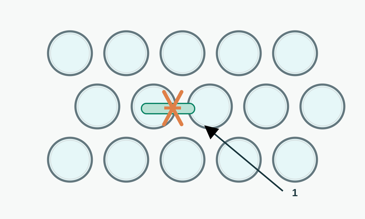
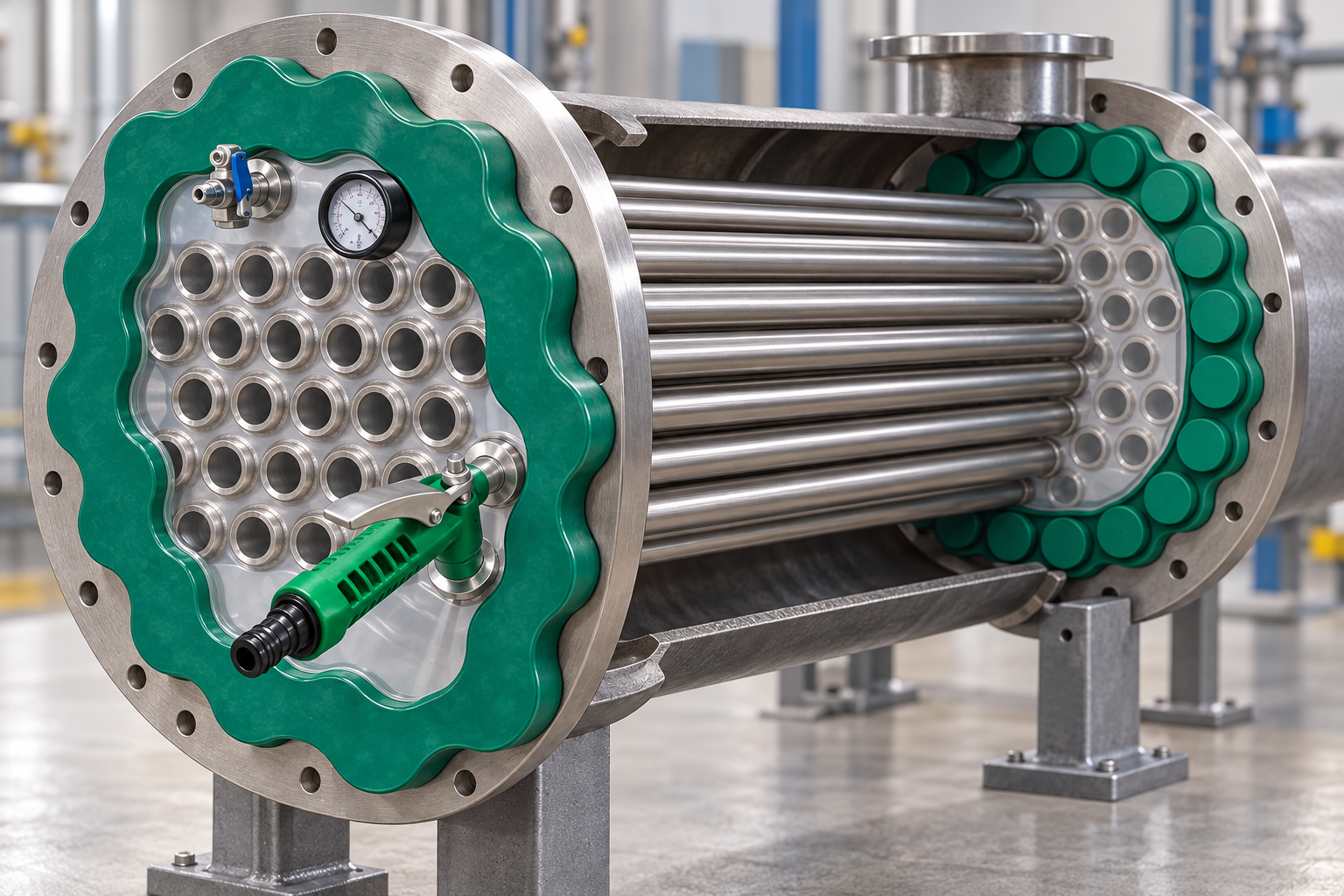
Closely spaced tube ends create a less obvious problem. A conventional vacuum box needs a continuous area for its elastomer seal. There may be too little exposed surface between neighboring tubes, and a soft seal can spread under compression, obstruct a weld or fail to seat consistently. The fixture described here moves the sealing boundary around a cluster of tubes, leaving the inner joints visible through a transparent window.
This article is an engineering explanation based on the manufacturer's account, a photograph of the finished fixture, its 18/38 drawing, and public standards information. It is not a test report. No vacuum setting, exposure time, indicator formulation, acceptance criterion, measured leak rate or field result has been supplied.
Fixture documented by the manufacturer
A two-sided fixture for a tightly packed tube bundle
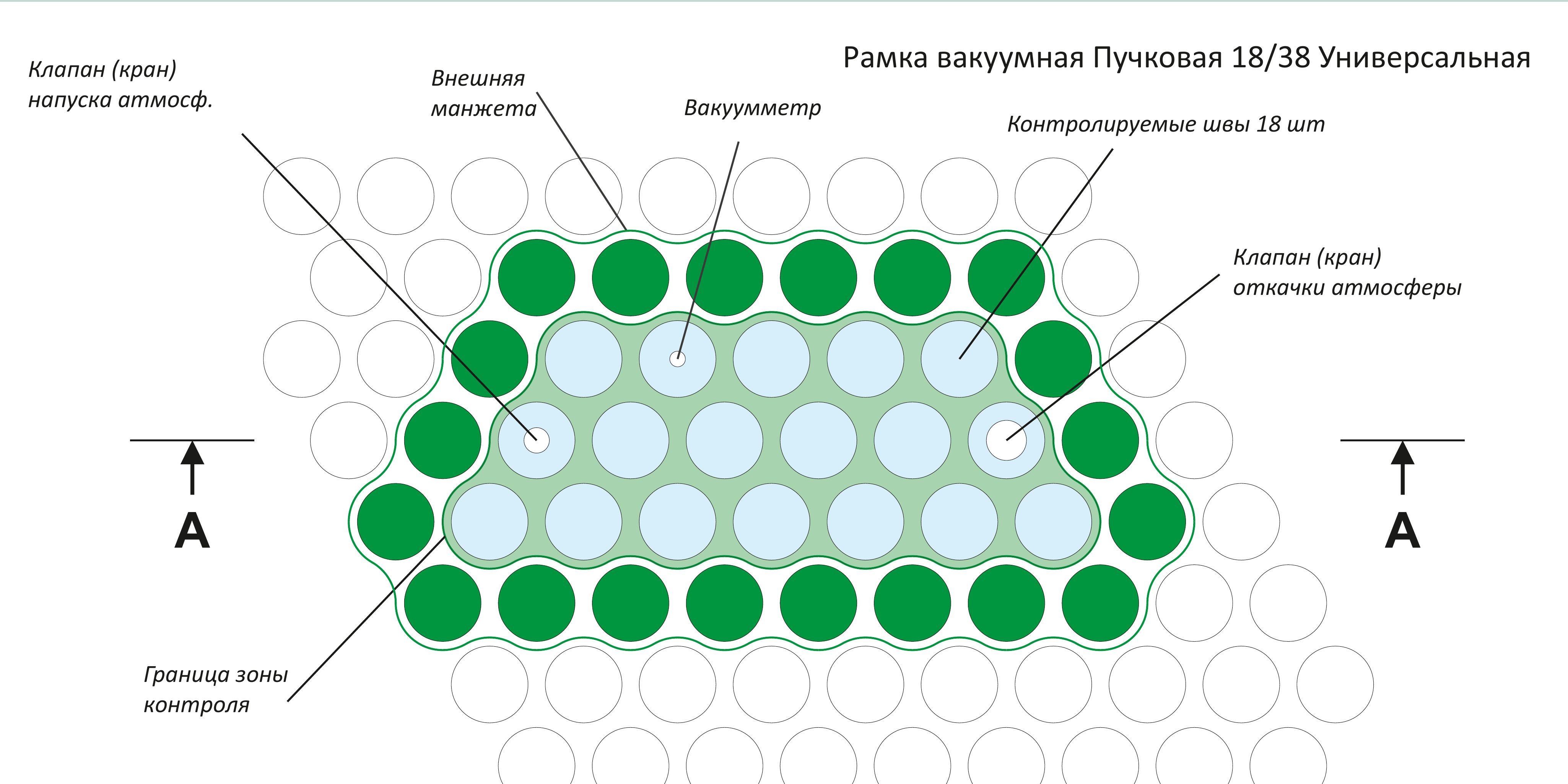
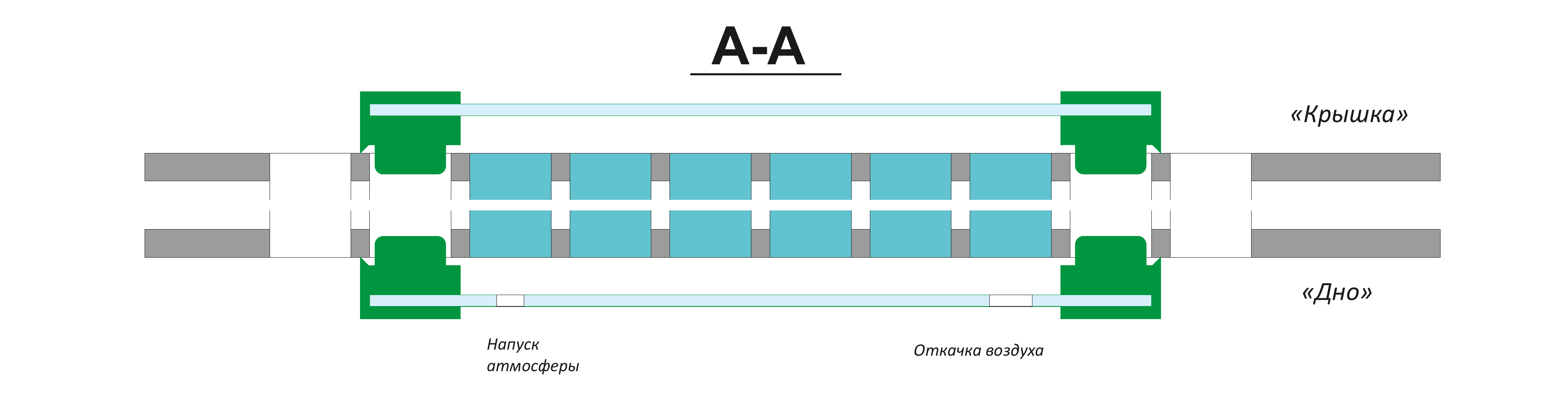
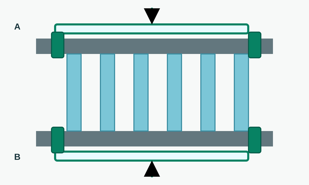
The supplied drawing is titled the 18/38 universal bundle vacuum frame. It shows 18 welds within the observation zone and a surrounding group of tube positions used to form the sealing boundary. Instead of trying to fit a separate narrow gasket around every weld, the design encloses a cluster and provides a larger, continuous inspection window.
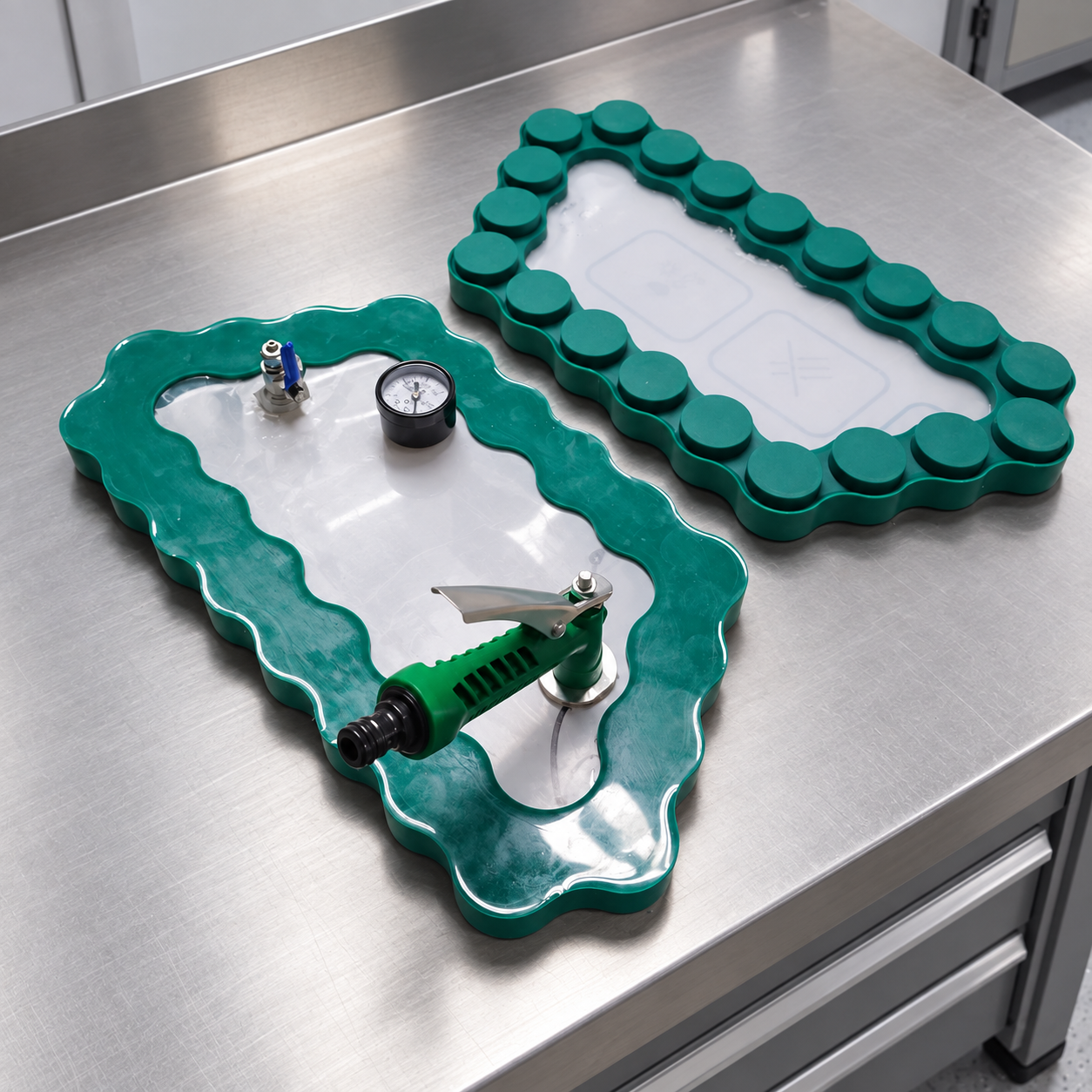
The original photograph documents two manufactured halves. One carries a clear window, gauge, valves and handle; the mating half has raised circular contact elements around its perimeter. According to the supplied description, the two parts operate simultaneously from opposite sides of the tube bundle. The drawing identifies a cover and base but does not document a particular operating setpoint or inspection outcome.
The notation 18/38 identifies this design example. It must not be treated as a standard inspection capacity for other exchangers: tube diameter, pitch, pattern, edge rows and access conditions can all change both the fixture shape and the number of welds exposed in one placement.
The tube-to-tubesheet joint as an inspection object
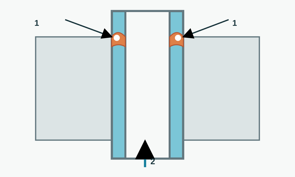
A tube sheet locates the tube ends and separates the fluid inside the tubes from the fluid on the shell side. Depending on the heat exchanger and its design code, the tube-to-tubesheet joint may have a structural function, a sealing function, or both. The first step in planning an examination is therefore to identify the actual joint specified in the drawings, the accessible weld surface and the side from which it can be observed.
At the tube mouth, the weld is a relatively small annular feature repeated many times across the sheet. Visual examination can assess visible surface characteristics, but an acceptable appearance does not demonstrate the absence of a through-leak. Local leak testing addresses a different question: whether gas can pass through a path ending in the indicator-coated area under the imposed test conditions.
Why a conventional seal may not fit
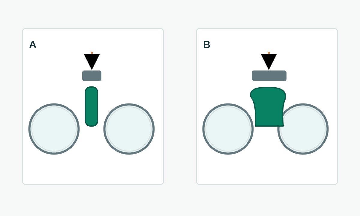
A local vacuum chamber normally seals against a continuous accessible surface around the target area. Closely spaced tube ends may leave too little free metal for the gasket footprint. Compression can cause an elastomer profile to spread sideways into the adjacent welds or tube mouths. The result may be an unstable chamber boundary, a partially hidden weld, or a leak at the fixture rather than at the inspected joint.
The problem cannot be solved responsibly by naming a different elastomer without examining the geometry. Relevant variables include actual pitch, tube projection, weld profile, gasket cross-section and stiffness, application load and surface condition. The supplied materials do not specify the exact grade of elastomer used in this fixture, so no material-performance claim is made here.
What the double-sided drawing actually shows
In plan view, the sealing outline follows the tube arrangement rather than a simple rectangle. It surrounds the group of welds left open for observation. Section A-A shows two fixture parts marked cover and base, with viewing elements and valves for evacuation and venting. A gauge provides a means of monitoring the chamber condition within the approved procedure.
The functional difference from a conventional vacuum box is the position of its seal: contact is established outside the densely packed central inspection group. A useful fixture must keep that perimeter continuous while allowing the examiner to see each required joint. The drawing alone cannot establish allowable vacuum, pump-down rate, observation time or acceptance limits; these are separate procedure and validation questions.
How bubble emission identifies a possible through-leak
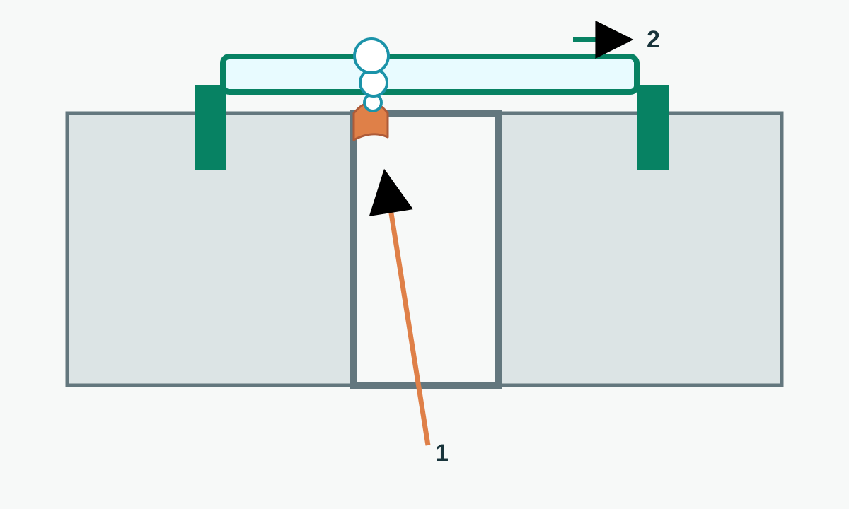
A suitable foam-forming indicator is applied to the accessible weld surfaces specified by the procedure. After the fixture is seated, air is evacuated from its local chamber. If gas can pass through a through-path and exit at an indicator-coated weld, it may create a growing bubble indication. The operator observes that location through the clear window and records it as required by the test instruction.
The technique is primarily a way to locate a possible leak, not to quantify its flow rate. ASTM E515 expressly distinguishes qualitative bubble-emission location from leakage-rate measurement. A bubble photograph on its own cannot establish a leak class or a numerical leakage rate: a different measurement method and controlled conditions would be needed for that claim.
Preparation and simultaneous access from both ends
Before an examination, the approved procedure must define the area, accessible tube ends, surface preparation, indicator suitability and equipment checks. Contact surfaces need to permit consistent seating, while contamination, old indicator residue and nearby obstructions can interfere with either the seal or the view. Exact cleaning requirements depend on the product materials and the controlling specification.
The examiner then applies the indicator to the designated welds, positions both fixture parts over the selected tube group, connects the evacuation line and checks the chamber condition. According to the case description, observation is simultaneous from both sides. This is a feature of the documented application, not a universal sequence for every heat exchanger: access, likely flow paths and the need for a second-side examination have to be established for the actual product.
This article intentionally gives no vacuum value, dwell period or pass/fail threshold. Those values would be guesses without the process sheet and validation records.
A weld indication versus an indication at the fixture edge
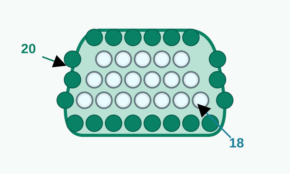
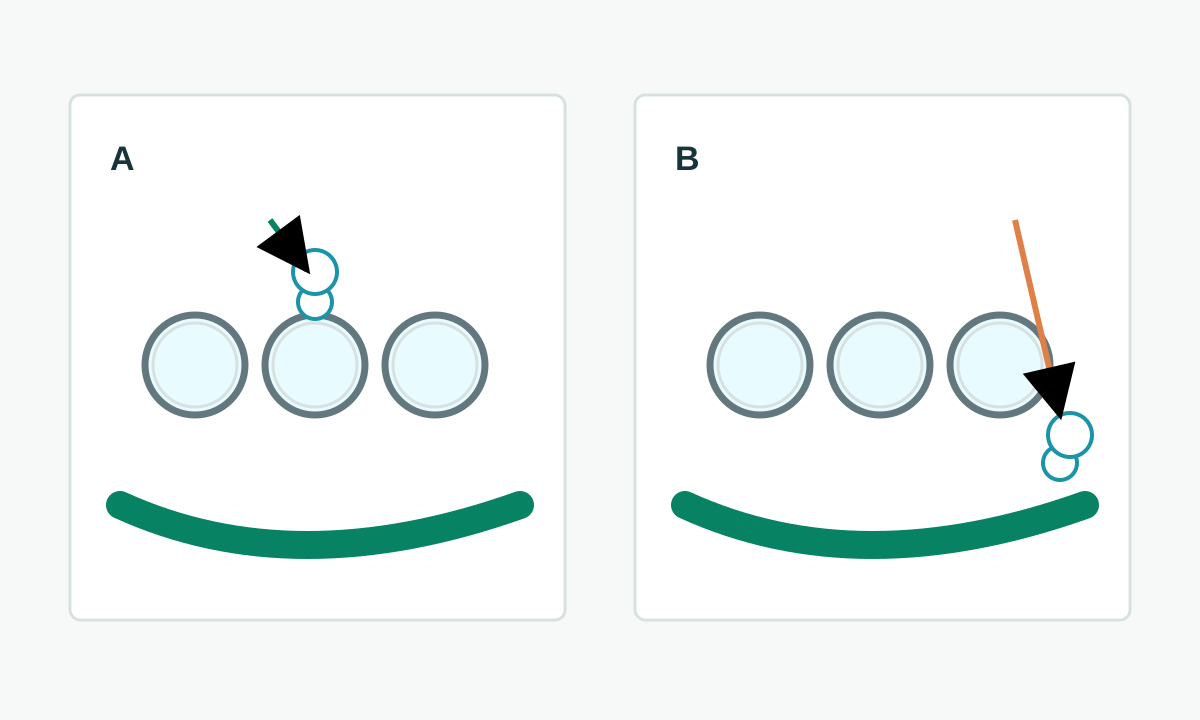
Location and development matter. Does a bubble form at one point on the weld and grow while the test conditions remain stable? Bubbles already present after indicator application, draining fluid or air entering at the fixture perimeter may look similar at first glance. An indication at the gasket boundary must not automatically be attributed to the adjacent tube weld.
A suspicious point is identified and documented as the governing procedure requires. Re-examination, if required, follows the same procedure after the chamber is vented. The diagram below is an aid to interpretation, not a substitute for a qualified examiner, the equipment check or the actual inspection record.
References: [10]
Planning complete coverage of a tube sheet
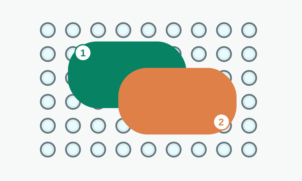
One placement exposes only a limited set of joints. A coverage plan should map each successive fixture position to the welds visible within it, the welds temporarily hidden under its perimeter and the amount of overlap required between positions. Edge rows, baffles or changes in the tube pattern deserve separate attention because they may not be accessible with the central fixture shape.
It would be incorrect to infer 100% inspection from the 18/38 drawing alone. Such a claim requires a plan that includes every specified joint and records showing that the plan was completed. Some areas may need a second fixture configuration or another agreed inspection method.
Why the fixture is engineered for each tube pattern
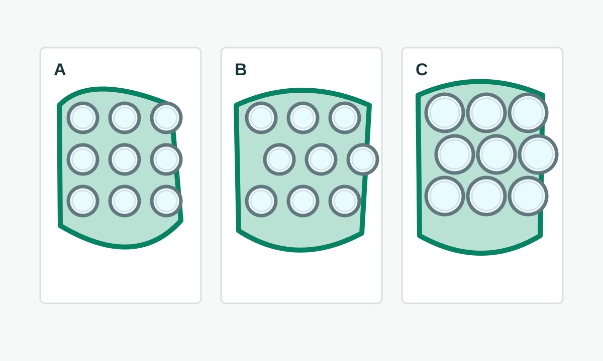
Exchangers with the same general purpose may use different tube outside diameters and pitches, square or staggered patterns, weld profiles, tube projections and distances to a sheet edge. Each variable changes where a continuous gasket can make reliable contact. A seal outline that works on one pattern can leave an open path or obstruct required welds on another.
Design input should include an anonymized tube-sheet drawing or model, tube diameters and pitch, projection at the ends, local obstacles, the specified weld set and access from both sides. From that information, the manufacturer can define one fixture or a complementary set and establish the intended sequence of placements. Two different tube-sheet drawings were supplied as geometry examples for this article; neither proves that the 18/38 fixture was used on that particular equipment.
Two different tube fields: why a fixture cannot simply be copied
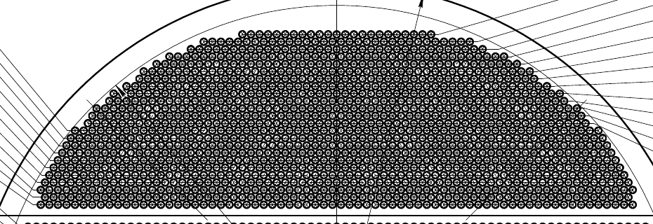
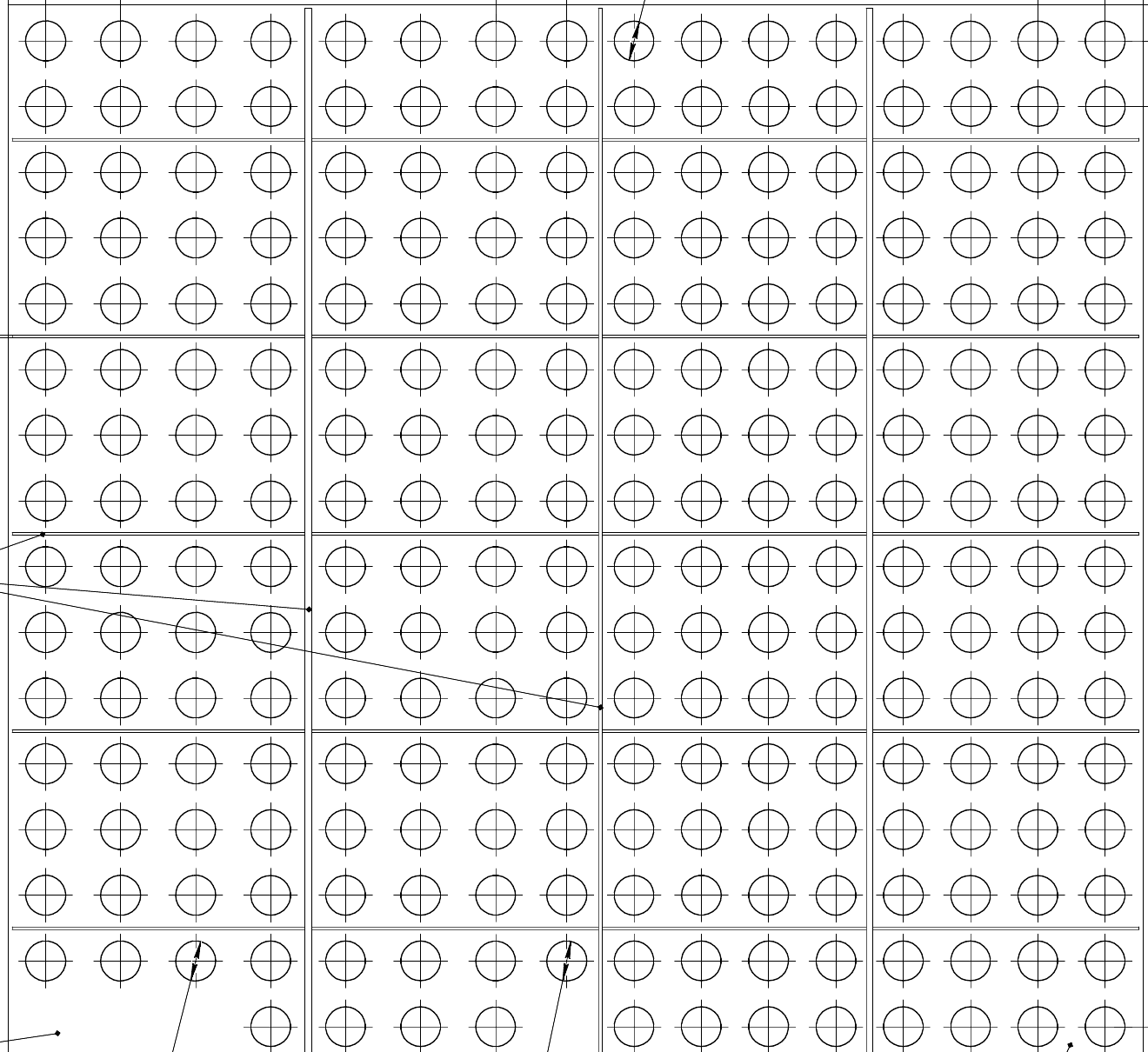
Two tube-sheet drawings supplied for background show markedly different geometries. One extract shows part of a circular field with many closely packed holes and a sector-like layout. The other shows a rectangular field of larger holes divided by structural lines. Even before a detailed fit study, their contact boundaries are plainly different: a gasket outline that follows one field cannot simply be scaled or transferred to the other.
These images are geometry examples only. They do not show the 18/38 fixture installed, prove that bubble testing was performed on either product, or supply enough information to calculate the actual usable contact width. A new fixture must be developed against the current drawing of the specific tube sheet, not by enlarging a photograph of an earlier frame.
Only cropped hole-pattern areas are shown here, without project identifiers, title blocks or customer details. Their role is to illustrate why individual geometry matters, not to connect either drawing to the documented 18/38 case.
Design inputs for a project-specific fixture
Tube outside diameter alone is not enough to define a workable seal. The tube-sheet extract should show pitch and layout, the usable footprint, tube projection, the specified weld profile and surfaces where gasket contact is permitted. Bolting, bridges, nozzles and other nearby features may limit access or the route of the vacuum connection. If the layout changes across the sheet, input is needed for each distinct zone rather than for a single representative cluster.
The inspection scope and manufacturing stage also matter. Access before final assembly may be very different from access after neighboring components are fitted. For a double-sided arrangement, the positions of both fixture parts have to be coordinated so the required welds remain observable and neither part conflicts with temporary supports or assembly tooling. This is an equipment-layout question as much as a gasket-design question.
The engineering output should therefore include the contact outline, window, valve and hose locations, plus a placement map. The responsible manufacturer must validate the proposed fixture and procedure to the extent required for the product before relying on them for inspection. A photograph of a prototype, or a fit to one drawing fragment, does not establish performance on another exchanger.
What an inspection procedure and record should define
A product-specific instruction needs to establish the method's applicability, surface preparation, indicator, fixture seating and seal check, differential pressure, observation period and response to an indication. Settings must be compatible with the exchanger design and materials. None of their numerical values can be responsibly supplied here because the approved instruction has not been provided.
Each result needs a reproducible weld location, whether by tube and row number, drawing coordinate or another project convention. The record should identify which welds were exposed at each placement and what was observed. A leak at the fixture perimeter must be distinguishable from an indication at a tube weld. Moving the fixture without a placement map and record can leave a row unexamined even when the operator has made many individual observations.
Acceptance criteria are defined in the applicable design, process or purchase documents; they do not follow automatically from an illustrative bubble diagram. Where repairs or repeat examinations are required, the instruction should specify how those steps are documented. This preserves the connection between an observation, a particular joint and the operation performed.
How local bubble testing relates to other examinations
Visual and dimensional examination assesses visible weld shape and surface condition. A local bubble-emission test asks whether a through-path produces an observable gas indication under the specified test conditions. Those are different quality characteristics. Ultrasonic, radiographic or other methods may be specified for internal discontinuities or different objectives, depending on the joint design and the controlling code.
A pressure test considers the equipment or a defined pressure boundary as a system under its own approved program. A result from one local group of tube welds does not become a conclusion about the entire heat exchanger. Quantitative leak-detection methods, when a leakage-rate limit is required, use their own equipment and acceptance rules. The proper combination of examinations follows the product risk, specification and physical access.
The defensible statement for the present technique is whether a bubble indication was or was not observed at the specified location under the approved conditions. A claim that an entire exchanger is leak-tight requires a broader body of evidence.
Standards and regulatory context without overclaiming
EN 1593 addresses bubble-emission leak-testing techniques, while ASTM E515 describes a qualitative practice for detecting or locating leaks. ISO 15614-8 concerns qualification of welding procedures for tube-to-tubeplate joints; it is not the operating instruction for this fixture. ISO 16812:2019 addresses shell-and-tube exchangers within its defined petroleum, petrochemical and natural-gas scope, not every exchanger sold worldwide.
For EU projects, the Pressure Equipment Directive 2014/68/EU is considered according to the equipment's actual scope and category. Turkey publishes corresponding pressure-equipment rules. These frameworks govern the relevant equipment and conformity assessment; they do not, merely by being mentioned, approve a custom bubble fixture or set its test parameters. For Russian projects, GOST 24054-80 and GOST R 51780-2001 inform general leak-test requirements and method selection, while GOST R ISO 15614-8-2026 addresses welding-procedure qualification.
The applicable design code, customer specification, inspection plan and acceptance procedure ultimately decide which tests are required for a particular exchanger. The standards discussed here are a source map for engineering review, not a certificate of compliance for an unspecified product.
What the available evidence does and does not establish
The supplied photograph and drawing establish that the fixture was made and show its design concept. They do not establish sensitivity, repeatability, defect-detection rate, acceptance of a particular heat exchanger or conformity of an entire installation with a pressure-equipment category. Accordingly, this article reports no invented vacuum setpoint, exposure time, measured leak or inspection result.
Bubble emission looks for a through-path in the accessible test zone. It does not replace examination for internal weld discontinuities, structural qualification of the joint or any full-equipment test required by the product specification. The inspection program must combine methods according to the service, design and governing documentation.
The practical conclusion: design the seal around the actual geometry
The dense-bundle case demonstrates a useful geometric approach. When a narrow conventional gasket cannot be placed reliably between tube ends, the inspection zone can instead be bounded around a group of surrounding tubes while the central welds remain visible. The documented double-sided arrangement addresses the access problem for this design, but suitability for another exchanger must be assessed rather than assumed.
Tube diameter, pitch and layout vary from project to project. RUNDT is ready to engineer the necessary vacuum-frame configuration for a customer's specific tube-sheet geometry, inspection scope and access conditions. Where one outline cannot cover all areas, a complementary set of frames can be developed from the drawings or model.
Questions and answers
How many welds can the fixture inspect in one placement?
The supplied 18/38 drawing shows 18 welds in its observation zone. The number for another exchanger depends on its tube pattern, the fixture design and the coverage plan.
Can one frame cover an entire tube sheet?
Not necessarily. Edge rows, changed pitch and local obstructions may require a different outline. Coverage must be demonstrated by an inspection map and records.
Does a bubble give a numerical leakage rate?
No. A bubble indication helps locate a possible through-leak. Quantitative leakage-rate measurement requires a separate method under defined conditions.
What information is needed for a custom frame?
Tube diameter and pitch, weld and free-surface geometry, access to both ends, obstacles, the required inspection areas and the controlling test specification. Customer identifiers can be removed from the drawing used for an initial discussion.
Primary sources and scope notes
Technical context was checked against the linked primary sources. Fixture details come from the supplied photograph, drawing and manufacturer account; unpublished test conditions and results are not inferred.
- [1] US DOE: Fundamentals Handbook, Heat Exchangers
- [2] Rosstandart: GOST 24054-80, general leak-testing requirements
- [3] Rosstandart: GOST R 51780-2001, selection of leak-testing methods
- [4] Rosstandart: GOST R 59286-2020, leak-testing terminology
- [5] Rosstandart: GOST 31842-2012, shell-and-tube exchangers within its stated scope
- [6] Rosstandart: GOST R ISO 15614-8-2026, tube-to-tubeplate welding procedure qualification
- [7] ISO 15614-8:2016: tube-to-tubeplate welding procedure qualification
- [8] ISO 16812:2019: shell-and-tube heat exchangers, defined industry scope
- [9] DIN Media: EN 1593, bubble emission leak testing
- [10] ASTM E515-11(2022): bubble emission techniques and their qualitative scope
- [11] EUR-Lex: Pressure Equipment Directive 2014/68/EU
- [12] Republic of Türkiye Ministry of Trade: pressure-equipment rules