
Briefly about the task
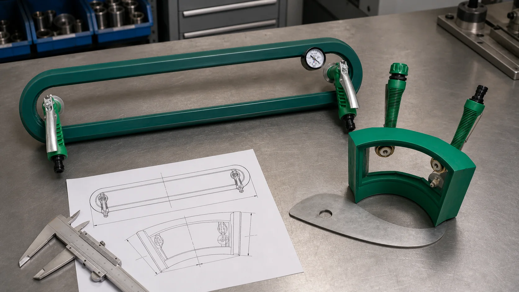
A standard flat, square, corner or tube frame covers typical applications. If the connection is located on a surface with a certain radius, there are ribs, fasteners or protruding elements nearby, the working contour is agreed upon according to the customer’s initial data.
The Insider Review does not require disclosure of the product's purpose or proprietary item information. Usually, an impersonal fragment of the drawing, dimensions of the control zone, radii, photographs of the layout or template and the requirements of the technological documentation are sufficient.
Engineering problem statement
From the controlled surface to the working geometry of the frame
First, determine what area should be visible in the window and where a continuous sealing contour can run. Then check whether adjacent structural elements interfere with the handles, fittings and hoses.
Based on this data, the closest standard design is selected or a frame is designed for a specific radius and available area. The shape is not assigned arbitrarily: it follows the geometry of the real zone that needs to be hermetically sealed.
Minimum set of initial data
For the first calculation it is useful to send a top view and a section through the surface. They should show a controlled seam, a free area for sealing and elements limiting the installation or relocation of the frame.
If the exact drawing cannot be transmitted, it is replaced by an impersonal sketch, dimensional template or photograph of the layout with a scale bar. It is critical to maintain the dimensions and relative position of the surfaces.
- joint type and seam direction;
- length and width of the observed area;
- radius or radii of the controlled surface;
- width of the free surface on both sides of the connection;
- height of seam reinforcement, fasteners and other projections;
- dimensions of available space for handles and hose;
- temperature, condition and surface material;
- vacuum requirements and applicable regulations.
What dimensions should not be replaced by an approximate photograph
Photography helps to understand the layout, but perspective distorts the dimensions and radii. For a pipe frame you need the outer diameter, for an angular frame - the magnitude and direction of the angle, for a curved surface - the radius and direction of curvature.
If the surface has a double curvature or a varying radius, one value is not enough. Several sections, a coordinate model, a control template, or another way to reproduce the geometry are coordinated.
- pipe outer diameter instead of nominal diameter;
- radius along the seal line, and not just along the axis of the seam;
- actual height of obstacles above the surface;
- minimum clearances for installation and relocation;
- tolerances and possible range of product geometries.
Position of handles, valves and hose
The operator holds the frame by two protruding handles. They contain pumping valves, and the hose is connected to the fitting of one of the handles. Therefore, in the technical specifications it is important to show from which side the operator approaches the product and where the hose can go.
If there is not enough space around the connection, the position of the handles is agreed upon separately. They should not rest against ribs, walls or fittings and should not cause the operator to apply load to a window, fixture or hose.
- operator approach side;
- ambidextrous access;
- hose exit direction;
- valve lever free play area;
- limits on overall frame height.
How the execution is coordinated
After analyzing the initial data, the working form, window dimensions, position of the seal, handles and measuring elements are agreed upon. Before production, the customer checks that the diagram takes into account adjacent elements and provides a clear sequence of rearrangement.
The resulting design is intended for the given geometry and conditions. If the diameter, radius, connection type or accessible area changes, the suitability of the frame must be re-evaluated.
Questions and Answers
Is it possible to order a frame without a complete drawing of the product?
Yes. For a preliminary assessment, an impersonal sketch or fragment with dimensions, radii, obstacles and a free zone around the connection is often sufficient.
Is a photo with a ruler enough?
It is useful for understanding the layout, but critical dimensions and radii must be specified separately. Perspective distortion does not allow reliable restoration of the working geometry.
Why do you need to show the operator's position?
A person holds the frame by two standard handles, controls the valves located on them and connects a hose to one of the handles. This requires free space.
Is it possible to make one frame for several radii?
Only if calculation and testing confirm acceptable fit over the entire range. For significantly different geometries, it is more reliable to use separate designs.
Open sources and explanations
Technical context verified against open primary sources. Information about the equipment is given according to the provided photograph, drawing and description of the manufacturer; missing modes and test results are not conjectured.