Briefly about the task
At oil and gas and oil transportation infrastructure facilities, tightness is required for welded joints of tanks, process pipelines and metal structures. During construction and renovation, some areas are accessible only from one side, and it is inconvenient or impossible to create pressure throughout the entire facility at an intermediate stage.
The vacuum chamber creates a vacuum only above the selected zone. A foam indicator applied to the seam makes the passage of air through the through discontinuity visible. The method identifies the location of a through leak; the cause of the indication and the condition of the connection are assessed as part of the approved non-destructive testing system.
The article separately describes a typical open scenario and information from TECH NK LLC on supplies to divisions of Transneft PJSC. The names of specific objects, routes, sections, modes and results of control are not disclosed.
Delivery experience according to TECH NK LLC
Oil transportation infrastructure: framework and RUNDT-XR
According to TECH NK LLC, RUNDT solutions were supplied to divisions of Transneft PJSC for specialized control tasks. A specific delivery may include vacuum frames for standard and special areas and a mobile installation RUNDT-XR; the actual packaging is determined by the order specification.
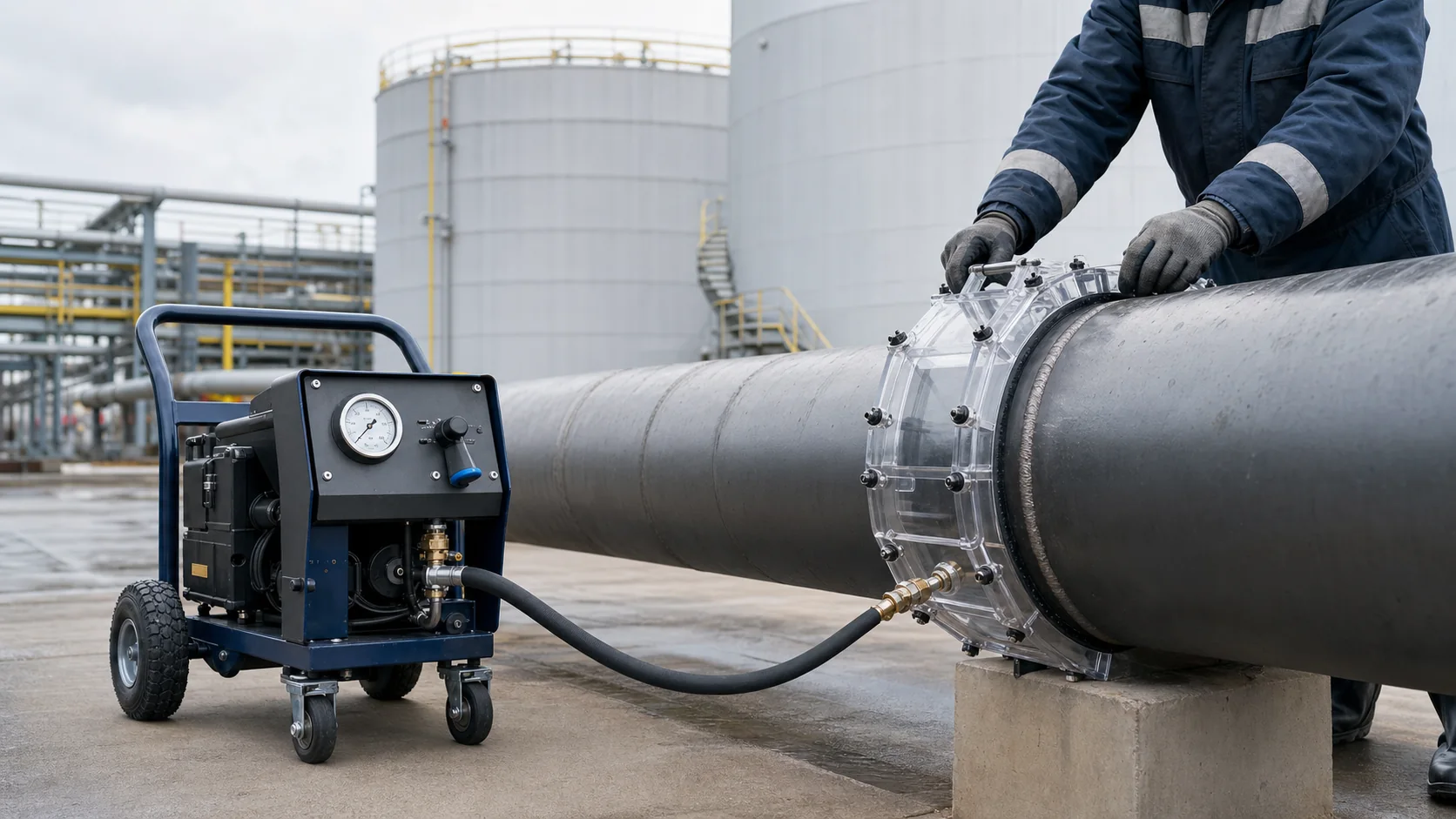
The RUNDT-XR is mounted on a two-wheel trolley with pneumatic wheels. The structure includes a vacuum pump, a distribution block with a vacuum gauge and shut-off valves, a filter-moisture separator and a hose 25 meters long. This arrangement allows the installation to be left on a stable platform, and the operator to work with the frame in a remote area.
Mention of other oil companies without confirmed publication rights has been intentionally excluded. The article describes the technology and industry challenges, but does not disclose the list of customers.
Which areas are controlled
The scope of control is established by design and regulatory documentation. Vacuum frames are especially useful for local welded joints and structures with one-way access.
- circumferential and longitudinal welded joints of large diameter pipes;
- sections of process pipelines and piping units;
- welded joints of the bottoms of vertical steel tanks (VS);
- connecting the tank wall to the bottom, if provided for by the technology;
- seams of sheet metal structures, caissons and gas tanks;
- local zones after repair, insertion or defect elimination.
Why a RUNDT-XR field installation is needed
On a tank farm or along a large structure, the operating points are distributed over a large area. It is inconvenient to carry the pump along with each frame change, so the installation and the working tool are separated by a long vacuum hose.
The trolley makes it easy to move the kit over concrete, soil and metal decks. The control unit allows you to connect and cut off the lines of the pump and frame, control the vacuum using a vacuum gauge and safely let in air before removing the chamber.
Vacuum frames are not automatically included in the universal basic set: they are selected for a flat seam, corner connection, outer diameter of the pipe or special geometry of the object.
Pipe circumferential weld frame
The ring connection requires a chamber whose seal follows the outside diameter of the pipe. A discrepancy between the radius leads to suction around the perimeter and does not allow the stable creation of a working vacuum.
When ordering, take into account the outer diameter, actual ovality, seam reinforcement height, surface condition and available installation area. If supports, bends or fittings are located nearby, additionally check the size of the frame and the direction of connection of the hose.
Tank Weld Inspection
On the bottom of the RVS, a flat frame is sequentially rearranged along the welded joint with overlapping zones. The long RUNDT-XR hose allows you to reduce the number of pump part relocations and work at a distance from the hatch or installation location.
Before testing, remove dirt, moisture and unevenness from the seal area. The foaming indicator is applied immediately before installing the camera. After creating a vacuum, the operator observes the seam for a time set by the technology, notes a stable indication and records the result.
Restrictions and safety
RUNDT-XR in its basic version is powered by a 220 V network. The placement of electrical equipment, use in a potentially explosive area, work permit, grounding and other measures are determined by the rules of a particular facility. The length of the hose does not automatically mean leaving the pump in any selected area.
Bubble-vacuum testing shows the presence of a through channel in the area being examined, but does not evaluate all internal defects in the welded joint. The method complements and does not replace visual measurement, ultrasonic, radiographic and other types of control, if they are provided for by the project.
Questions and Answers
Is it possible to check the circumferential weld of a pipe with a flat frame?
On a large-diameter pipe and a short section, this is sometimes only possible with a small local curvature, but it is more reliable to use a frame with a radius for the outer diameter of the pipe.
Is RUNDT-XR suitable for RVS underbody?
Yes, this is one of the typical scenarios: the installation remains on site, and the frame is connected with a 25-meter hose and sequentially rearranged along the welded joints.
Does the method detect undercooking?
It will only detect lack of fusion when the defect forms a through channel through the structure being monitored. Non-through internal discontinuities require other inspection methods.
Can I work in a hazardous area?
Tolerance is determined by equipment design, zone classification, and facility regulations. A basic network installation cannot be considered explosion-proof without appropriate confirmation.
What data is needed to select a kit?
Requires site type, connection geometry and dimensions, pipe outside diameter, access conditions, power availability, required hose length, and applicable codes.
Open sources and explanations
Technical context verified against open primary sources. Information about the equipment is given according to the provided photograph, drawing and description of the manufacturer; missing modes and test results are not conjectured.